
¿Quieres darle un toque Vintage a tu cuarto o la sala de tu casa? ¡Haz tu propio reloj digital con un diseño retro y moderno! Con este proyecto aprenderás a hacer un accesorio que llamará la atención de todos tus invitados.
Este proyecto consiste en la construcción de un reloj digital basado en seis matrices de LEDs. Conserva un estilo retro y está hecho para que sea fácil de pintar, para que tenga tu propio estilo. El reloj utiliza un módulo RTC para mantener en su memoria la hora. La tarjeta Arduino se encargará de actualizar la hora en las matrices de LEDs para que puedas usar tu reloj.
Recuerda leer las consideraciones de seguridad antes de empezar cualquier proyecto: (leer)
Lo primero que debes hacer es conectar las 6 matrices de LEDs entre ellas para que la comunicación entre la tarjeta Arduino y las matrices sea efectiva. Para esto, debes conectar las 6 matrices con ayuda de los cables jumper hembra-hembra. Empieza por conectar dos matrices como se muestra en la siguiente imagen. Ten en cuenta que los colores de los cables en la imagen son solo un ejemplo. Puedes hacer las conexiones con los colores que desees. Los cables jumpers vienen unidos en grupos de 10, pero puedes separarlos entre ellos para que la conexión sea más sencilla. No te asustes si te sobran cables jumpers, ya que algunas veces se incluyen repuestos.

Repite el proceso con una tercera matriz de la misma forma en la que conectaste las dos primeras. Estas tres matrices de LEDs serán el lado izquierdo de tu reloj digital. Conecta las tres matrices restantes entre ellas para obtener dos grupos de tres matrices como se muestra en la siguiente imagen:

A partir de este momento, llamaremos las matrices con números de acuerdo a los que se muestran en la siguiente imagen:

Ahora, es necesario conectar la matriz 3 con la matriz 4. Debido a la posición que tendrán estas matrices dentro de tu reloj, es necesario realizar una extensión de los cables jumper. Para esto, conecta cinco cables jumper macho-hembra con cinco cables jumper hembra-hembra. Tendrás como resultado cinco cables jumper hembra-hembra del doble de longitud. Utiliza los cinco cables largos para unir la matriz 3 con la matriz 4, siguiendo las mismas conexiones que hiciste con todas las demás. Si hiciste todo bien tendrás una fila de seis matrices de LEDs con un inicio (la matriz 1) y un final (la matriz 6). El inicio será el que conectarás a tu tarjeta Arduino.
Es importante que te asegures de que la matriz 3 y 4 estén conectadas con las extensiones que mencionamos anteriormente. De lo contrario, no vas a poder ensamblar el reloj.

Utiliza los jumpers macho-hembra para conectar el inicio de tus matrices de LEDs (matriz 1) y el RTC a tu tarjeta Arduino como se muestra en la siguiente imagen. Ten en cuenta que los colores de los cables en la imagen son solo un ejemplo. Puedes hacer las conexiones con los colores que desees. Los cables jumpers vienen unidos en grupos de 10, pero puedes separarlos entre ellos para que la conexión sea más sencilla. No te asustes si te sobran cables jumpers, ya que algunas veces se incluyen repuestos.

Antes de seguir, revisa que las conexiones que hiciste correspondan a las siguientes:
Antes de cargar un código para programar tu tarjeta Arduino, es necesario que instales las librerías para que éste funcione. Asegúrate de que tienes instalado el programa IDE de Arduino en tu computador. Si no sabes cómo hacerlo, puedes revisar el tutorial de instalación en el siguiente link, que te va a enseñar a hacerlo, paso a paso.
Para este proyecto, necesitas instalar la librería “LedControlMS.h” la cual puedes descargar del siguiente link . Si no sabes cómo instalar una librería, asegúrate de seguir el tutorial que podrás encontrar en este link .
Para cuadrar la hora de tu reloj, es necesario que programes el módulo RTC con ayuda de tu tarjeta Arduino. Para ello, conecta tu tarjeta Arduino al computador con el cable USB, abre el programa de computador IDE de Arduino e inicia un proyecto nuevo. Copia y pega el siguiente código:
// DS1302 RTC // ---------- // // Open Source / Public Domain // // Version 1 // By arduino.cc user "Krodal". // June 2012 // Using Arduino 1.0.1 // Version 2 // By arduino.cc user "Krodal" // March 2013 // Using Arduino 1.0.3, 1.5.2 // The code is no longer compatible with older versions. // Added bcd2bin, bin2bcd_h, bin2bcd_l // A few minor changes. // // // Documentation: datasheet // // The DS1302 uses a 3-wire interface: // - bidirectional data. // - clock // - chip select // It is not I2C, not OneWire, and not SPI. // So the standard libraries can not be used. // Even the shiftOut() function is not used, since it // could be too fast (it might be slow enough, // but that's not certain). // // I wrote my own interface code according to the datasheet. // Any three pins of the Arduino can be used. // See the first defines below this comment, // to set your own pins. // // The "Chip Enable" pin was called "/Reset" before. // // The chip has internal pull-down registers. // This keeps the chip disabled, even if the pins of // the Arduino are floating. // // // Range // ----- // seconds : 00-59 // minutes : 00-59 // hour : 1-12 or 0-23 // date : 1-31 // month : 1-12 // day : 1-7 // year : 00-99 // // // Burst mode // ---------- // In burst mode, all the clock data is read at once. // This is to prevent a rollover of a digit during reading. // The read data is from an internal buffer. // // The burst registers are commands, rather than addresses. // Clock Data Read in Burst Mode // Start by writing 0xBF (as the address), // after that: read clock data // Clock Data Write in Burst Mode // Start by writing 0xBE (as the address), // after that: write clock data // Ram Data Read in Burst Mode // Start by writing 0xFF (as the address), // after that: read ram data // Ram Data Write in Burst Mode // Start by writing 0xFE (as the address), // after that: write ram data // // // Ram // --- // The DS1302 has 31 of ram, which can be used to store data. // The contents will be lost if the Arduino is off, // and the backup battery gets empty. // It is better to store data in the EEPROM of the Arduino. // The burst read or burst write for ram is not implemented // in this code. // // // Trickle charge // -------------- // The DS1302 has a build-in trickle charger. // That can be used for example with a lithium battery // or a supercap. // Using the trickle charger has not been implemented // in this code. // // Set your own pins with these defines ! #define DS1302_SCLK_PIN 6 // Arduino pin for the Serial Clock #define DS1302_IO_PIN 7 // Arduino pin for the Data I/O #define DS1302_CE_PIN 8 // Arduino pin for the Chip Enable // Macros to convert the bcd values of the registers to normal // integer variables. // The code uses separate variables for the high byte and the low byte // of the bcd, so these macros handle both bytes separately. #define bcd2bin(h,l) (((h)*10) + (l)) #define bin2bcd_h(x) ((x)/10) #define bin2bcd_l(x) ((x)%10) // Register names. // Since the highest bit is always '1', // the registers start at 0x80 // If the register is read, the lowest bit should be '1'. #define DS1302_SECONDS 0x80 #define DS1302_MINUTES 0x82 #define DS1302_HOURS 0x84 #define DS1302_DATE 0x86 #define DS1302_MONTH 0x88 #define DS1302_DAY 0x8A #define DS1302_YEAR 0x8C #define DS1302_ENABLE 0x8E #define DS1302_TRICKLE 0x90 #define DS1302_CLOCK_BURST 0xBE #define DS1302_CLOCK_BURST_WRITE 0xBE #define DS1302_CLOCK_BURST_READ 0xBF #define DS1302_RAMSTART 0xC0 #define DS1302_RAMEND 0xFC #define DS1302_RAM_BURST 0xFE #define DS1302_RAM_BURST_WRITE 0xFE #define DS1302_RAM_BURST_READ 0xFF // Defines for the bits, to be able to change // between bit number and binary definition. // By using the bit number, using the DS1302 // is like programming an AVR microcontroller. // But instead of using "(1<<X)", or "_BV(X)", // the Arduino "bit(X)" is used. #define DS1302_D0 0 #define DS1302_D1 1 #define DS1302_D2 2 #define DS1302_D3 3 #define DS1302_D4 4 #define DS1302_D5 5 #define DS1302_D6 6 #define DS1302_D7 7 // Bit for reading (bit in address) #define DS1302_READBIT DS1302_D0 // READBIT=1: read instruction // Bit for clock (0) or ram (1) area, // called R/C-bit (bit in address) #define DS1302_RC DS1302_D6 // Seconds Register #define DS1302_CH DS1302_D7 // 1 = Clock Halt, 0 = start // Hour Register #define DS1302_AM_PM DS1302_D5 // 0 = AM, 1 = PM #define DS1302_12_24 DS1302_D7 // 0 = 24 hour, 1 = 12 hour // Enable Register #define DS1302_WP DS1302_D7 // 1 = Write Protect, 0 = enabled // Trickle Register #define DS1302_ROUT0 DS1302_D0 #define DS1302_ROUT1 DS1302_D1 #define DS1302_DS0 DS1302_D2 #define DS1302_DS1 DS1302_D2 #define DS1302_TCS0 DS1302_D4 #define DS1302_TCS1 DS1302_D5 #define DS1302_TCS2 DS1302_D6 #define DS1302_TCS3 DS1302_D7 // Structure for the first 8 registers. // These 8 bytes can be read at once with // the 'clock burst' command. // Note that this structure contains an anonymous union. // It might cause a problem on other compilers. typedef struct ds1302_struct { uint8_t Seconds:4; // low decimal digit 0-9 uint8_t Seconds10:3; // high decimal digit 0-5 uint8_t CH:1; // CH = Clock Halt uint8_t Minutes:4; uint8_t Minutes10:3; uint8_t reserved1:1; union { struct { uint8_t Hour:4; uint8_t Hour10:2; uint8_t reserved2:1; uint8_t hour_12_24:1; // 0 for 24 hour format } h24; struct { uint8_t Hour:4; uint8_t Hour10:1; uint8_t AM_PM:1; // 0 for AM, 1 for PM uint8_t reserved2:1; uint8_t hour_12_24:1; // 1 for 12 hour format } h12; }; uint8_t Date:4; // Day of month, 1 = first day uint8_t Date10:2; uint8_t reserved3:2; uint8_t Month:4; // Month, 1 = January uint8_t Month10:1; uint8_t reserved4:3; uint8_t Day:3; // Day of week, 1 = first day (any day) uint8_t reserved5:5; uint8_t Year:4; // Year, 0 = year 2000 uint8_t Year10:4; uint8_t reserved6:7; uint8_t WP:1; // WP = Write Protect }; void setup() { ds1302_struct rtc; Serial.begin(115200); Serial.println(F("DS1302 Real Time Clock")); Serial.println(F("Version 2, March 2013")); // Start by clearing the Write Protect bit // Otherwise the clock data cannot be written // The whole register is written, // but the WP-bit is the only bit in that register. DS1302_write (DS1302_ENABLE, 0); // Disable Trickle Charger. DS1302_write (DS1302_TRICKLE, 0x00); // Remove the next define, // after the right date and time are set. #define SET_DATE_TIME_JUST_ONCE #ifdef SET_DATE_TIME_JUST_ONCE // Fill these variables with the date and time. int seconds, minutes, hours, dayofweek, dayofmonth, month, year; // Example for april 15, 2013, 10:08, monday is 2nd day of Week. // Set your own time and date in these variables. seconds = 0; minutes = 07; hours = 15; dayofweek = 7; // Day of week, any day can be first, counts 1...7 dayofmonth = 23; // Day of month, 1...31 month = 4; // month 1...12 year = 2017; // Set a time and date // This also clears the CH (Clock Halt) bit, // to start the clock. // Fill the structure with zeros to make // any unused bits zero memset ((char *) &rtc, 0, sizeof(rtc)); rtc.Seconds = bin2bcd_l( seconds); rtc.Seconds10 = bin2bcd_h( seconds); rtc.CH = 0; // 1 for Clock Halt, 0 to run; rtc.Minutes = bin2bcd_l( minutes); rtc.Minutes10 = bin2bcd_h( minutes); // To use the 12 hour format, // use it like these four lines: // rtc.h12.Hour = bin2bcd_l( hours); // rtc.h12.Hour10 = bin2bcd_h( hours); // rtc.h12.AM_PM = 0; // AM = 0 // rtc.h12.hour_12_24 = 1; // 1 for 24 hour format rtc.h24.Hour = bin2bcd_l( hours); rtc.h24.Hour10 = bin2bcd_h( hours); rtc.h24.hour_12_24 = 0; // 0 for 24 hour format rtc.Date = bin2bcd_l( dayofmonth); rtc.Date10 = bin2bcd_h( dayofmonth); rtc.Month = bin2bcd_l( month); rtc.Month10 = bin2bcd_h( month); rtc.Day = dayofweek; rtc.Year = bin2bcd_l( year - 2000); rtc.Year10 = bin2bcd_h( year - 2000); rtc.WP = 0; // Write all clock data at once (burst mode). DS1302_clock_burst_write( (uint8_t *) &rtc); #endif } void loop() { ds1302_struct rtc; char buffer[80]; // the code uses 70 characters. // Read all clock data at once (burst mode). DS1302_clock_burst_read( (uint8_t *) &rtc); sprintf( buffer, "Time = %02d:%02d:%02d, ", \ bcd2bin( rtc.h24.Hour10, rtc.h24.Hour), \ bcd2bin( rtc.Minutes10, rtc.Minutes), \ bcd2bin( rtc.Seconds10, rtc.Seconds)); Serial.print(buffer); sprintf(buffer, "Date(day of month) = %d, Month = %d, " \ "Day(day of week) = %d, Year = %d", \ bcd2bin( rtc.Date10, rtc.Date), \ bcd2bin( rtc.Month10, rtc.Month), \ rtc.Day, \ 2000 + bcd2bin( rtc.Year10, rtc.Year)); Serial.println( buffer); delay( 5000); } // -------------------------------------------------------- // DS1302_clock_burst_read // // This function reads 8 bytes clock data in burst mode // from the DS1302. // // This function may be called as the first function, // also the pinMode is set. // void DS1302_clock_burst_read( uint8_t *p) { int i; _DS1302_start(); // Instead of the address, // the CLOCK_BURST_READ command is issued // the I/O-line is released for the data _DS1302_togglewrite( DS1302_CLOCK_BURST_READ, true); for( i=0; i< 8; i++) { *p++ = _DS1302_toggleread(); } _DS1302_stop(); } // -------------------------------------------------------- // DS1302_clock_burst_write // // This function writes 8 bytes clock data in burst mode // to the DS1302. // // This function may be called as the first function, // also the pinMode is set. // void DS1302_clock_burst_write( uint8_t *p) { int i; _DS1302_start(); // Instead of the address, // the CLOCK_BURST_WRITE command is issued. // the I/O-line is not released _DS1302_togglewrite( DS1302_CLOCK_BURST_WRITE, false); for( i=0; i< 8; i++) { // the I/O-line is not released _DS1302_togglewrite( *p++, false); } _DS1302_stop(); } // -------------------------------------------------------- // DS1302_read // // This function reads a byte from the DS1302 // (clock or ram). // // The address could be like "0x80" or "0x81", // the lowest bit is set anyway. // // This function may be called as the first function, // also the pinMode is set. // uint8_t DS1302_read(int address) { uint8_t data; // set lowest bit (read bit) in address bitSet( address, DS1302_READBIT); _DS1302_start(); // the I/O-line is released for the data _DS1302_togglewrite( address, true); data = _DS1302_toggleread(); _DS1302_stop(); return (data); } // -------------------------------------------------------- // DS1302_write // // This function writes a byte to the DS1302 (clock or ram). // // The address could be like "0x80" or "0x81", // the lowest bit is cleared anyway. // // This function may be called as the first function, // also the pinMode is set. // void DS1302_write( int address, uint8_t data) { // clear lowest bit (read bit) in address bitClear( address, DS1302_READBIT); _DS1302_start(); // don't release the I/O-line _DS1302_togglewrite( address, false); // don't release the I/O-line _DS1302_togglewrite( data, false); _DS1302_stop(); } // -------------------------------------------------------- // _DS1302_start // // A helper function to setup the start condition. // // An 'init' function is not used. // But now the pinMode is set every time. // That's not a big deal, and it's valid. // At startup, the pins of the Arduino are high impedance. // Since the DS1302 has pull-down resistors, // the signals are low (inactive) until the DS1302 is used. void _DS1302_start( void) { digitalWrite( DS1302_CE_PIN, LOW); // default, not enabled pinMode( DS1302_CE_PIN, OUTPUT); digitalWrite( DS1302_SCLK_PIN, LOW); // default, clock low pinMode( DS1302_SCLK_PIN, OUTPUT); pinMode( DS1302_IO_PIN, OUTPUT); digitalWrite( DS1302_CE_PIN, HIGH); // start the session delayMicroseconds( 4); // tCC = 4us } // -------------------------------------------------------- // _DS1302_stop // // A helper function to finish the communication. // void _DS1302_stop(void) { // Set CE low digitalWrite( DS1302_CE_PIN, LOW); delayMicroseconds( 4); // tCWH = 4us } // -------------------------------------------------------- // _DS1302_toggleread // // A helper function for reading a byte with bit toggle // // This function assumes that the SCLK is still high. // uint8_t _DS1302_toggleread( void) { uint8_t i, data; data = 0; for( i = 0; i <= 7; i++) { // Issue a clock pulse for the next databit. // If the 'togglewrite' function was used before // this function, the SCLK is already high. digitalWrite( DS1302_SCLK_PIN, HIGH); delayMicroseconds( 1); // Clock down, data is ready after some time. digitalWrite( DS1302_SCLK_PIN, LOW); delayMicroseconds( 1); // tCL=1000ns, tCDD=800ns // read bit, and set it in place in 'data' variable bitWrite( data, i, digitalRead( DS1302_IO_PIN)); } return( data); } // -------------------------------------------------------- // _DS1302_togglewrite // // A helper function for writing a byte with bit toggle // // The 'release' parameter is for a read after this write. // It will release the I/O-line and will keep the SCLK high. // void _DS1302_togglewrite( uint8_t data, uint8_t release) { int i; for( i = 0; i <= 7; i++) { // set a bit of the data on the I/O-line digitalWrite( DS1302_IO_PIN, bitRead(data, i)); delayMicroseconds( 1); // tDC = 200ns // clock up, data is read by DS1302 digitalWrite( DS1302_SCLK_PIN, HIGH); delayMicroseconds( 1); // tCH = 1000ns, tCDH = 800ns if( release && i == 7) { // If this write is followed by a read, // the I/O-line should be released after // the last bit, before the clock line is made low. // This is according the datasheet. // I have seen other programs that don't release // the I/O-line at this moment, // and that could cause a shortcut spike // on the I/O-line. pinMode( DS1302_IO_PIN, INPUT); // For Arduino 1.0.3, removing the pull-up is no longer needed. // Setting the pin as 'INPUT' will already remove the pull-up. // digitalWrite (DS1302_IO, LOW); // remove any pull-up } else { digitalWrite( DS1302_SCLK_PIN, LOW); delayMicroseconds( 1); // tCL=1000ns, tCDD=800ns } } }Copiar todo
Para editar la hora que trae por defecto tu RTC, es necesario que primero puedas ver el número de las líneas en el programa de computador IDE de Arduino. Esto te ayudará a encontrar más rápido la sección que debes editar. Para esto, haz click en el menú de “File” y “Preferences” dentro del programa IDE de Arduino, como se muestra en la siguiente imagen:
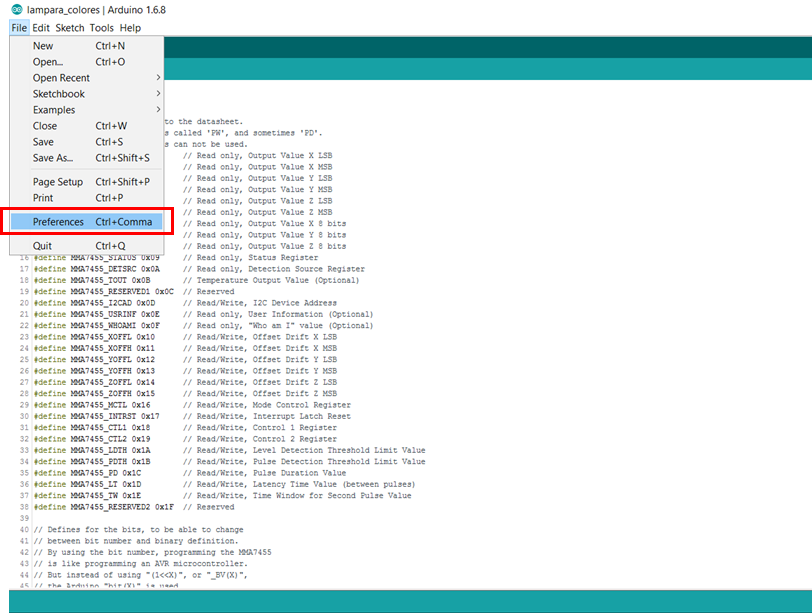
Activa la opción de mostrar el número de líneas al seleccionar el recuadro que dice “Display line numbers” y presiona "OK".

Ahora busca cerca a la línea número 250. Deberás encontrar la siguiente sección del código:

Cambia los valores de “hour” y ”minutes” a la hora actual. Por ejemplo, si son las 10:30 de la noche, pon el número 22 en “hour” (formato 24 horas) y el número 30 en “minutes”. Asegúrate de que, al cambiar la hora, haya un punto y coma (;) después del número que escribiste. Esto es importante para evitar que haya un error en el momento de compilar y cargar el código a tu tarjeta Arduino. Este código utiliza la tarjeta Arduino para programar tu módulo RTC. Una vez la hora queda guardada en el RTC, éste sigue contando la hora incluso cuando se encuentre desconectado. Esto sucede gracias a la pila de reloj que trae tu módulo RTC. Sube el programa como se explica en el siguiente link.
Recuerda revisar en la consola del programa IDE de Arduino que no aparezcan errores. ¡Asegúrate de esto antes de avanzar en el proyecto!
Sin desconectar la tarjeta Arduino de tu computador, abre un proyecto nuevo en el programa de computador IDE de Arduino. Para esto, presiona las teclas “ctrl” y “n” al mismo tiempo. Copia y pega el siguiente código.
// ========================================================================== // == Reloj de matriz de LED ============================================== // // ===== Librerias=========================================================== #include < LedControlMS.h> // Para el manejo del driver MAX1769 #include < binary.h> #include < avr/pgmspace.h> //#include "Wire.h" // ===== DEFINICIONES ============================================================ #define DS3231_I2C_ADDRESS 0x68 #define _DST 1 // DST es 1 hora adelante del tiempo en la memoria del RTC #define NB 6 // numero de matrices de LED // DS1302 RTC // ---------- // // Open Source / Public Domain // // Version 1 // By arduino.cc user "Krodal". // June 2012 // Using Arduino 1.0.1 // Version 2 // By arduino.cc user "Krodal" // March 2013 // Using Arduino 1.0.3, 1.5.2 // The code is no longer compatible with older versions. // Added bcd2bin, bin2bcd_h, bin2bcd_l // A few minor changes. // // // Documentation: datasheet // // The DS1302 uses a 3-wire interface: // - bidirectional data. // - clock // - chip select // It is not I2C, not OneWire, and not SPI. // So the standard libraries can not be used. // Even the shiftOut() function is not used, since it // could be too fast (it might be slow enough, // but that's not certain). // // I wrote my own interface code according to the datasheet. // Any three pins of the Arduino can be used. // See the first defines below this comment, // to set your own pins. // // The "Chip Enable" pin was called "/Reset" before. // // The chip has internal pull-down registers. // This keeps the chip disabled, even if the pins of // the Arduino are floating. // // // Range // ----- // seconds : 00-59 // minutes : 00-59 // hour : 1-12 or 0-23 // date : 1-31 // month : 1-12 // day : 1-7 // year : 00-99 // // // Burst mode // ---------- // In burst mode, all the clock data is read at once. // This is to prevent a rollover of a digit during reading. // The read data is from an internal buffer. // // The burst registers are commands, rather than addresses. // Clock Data Read in Burst Mode // Start by writing 0xBF (as the address), // after that: read clock data // Clock Data Write in Burst Mode // Start by writing 0xBE (as the address), // after that: write clock data // Ram Data Read in Burst Mode // Start by writing 0xFF (as the address), // after that: read ram data // Ram Data Write in Burst Mode // Start by writing 0xFE (as the address), // after that: write ram data // // // Ram // --- // The DS1302 has 31 of ram, which can be used to store data. // The contents will be lost if the Arduino is off, // and the backup battery gets empty. // It is better to store data in the EEPROM of the Arduino. // The burst read or burst write for ram is not implemented // in this code. // // // Trickle charge // -------------- // The DS1302 has a build-in trickle charger. // That can be used for example with a lithium battery // or a supercap. // Using the trickle charger has not been implemented // in this code. // // Set your own pins with these defines ! #define DS1302_SCLK_PIN 6 // Arduino pin for the Serial Clock #define DS1302_IO_PIN 7 // Arduino pin for the Data I/O #define DS1302_CE_PIN 8 // Arduino pin for the Chip Enable // Macros to convert the bcd values of the registers to normal // integer variables. // The code uses separate variables for the high byte and the low byte // of the bcd, so these macros handle both bytes separately. #define bcd2bin(h,l) (((h)*10) + (l)) #define bin2bcd_h(x) ((x)/10) #define bin2bcd_l(x) ((x)%10) // Register names. // Since the highest bit is always '1', // the registers start at 0x80 // If the register is read, the lowest bit should be '1'. #define DS1302_SECONDS 0x80 #define DS1302_MINUTES 0x82 #define DS1302_HOURS 0x84 #define DS1302_DATE 0x86 #define DS1302_MONTH 0x88 #define DS1302_DAY 0x8A #define DS1302_YEAR 0x8C #define DS1302_ENABLE 0x8E #define DS1302_TRICKLE 0x90 #define DS1302_CLOCK_BURST 0xBE #define DS1302_CLOCK_BURST_WRITE 0xBE #define DS1302_CLOCK_BURST_READ 0xBF #define DS1302_RAMSTART 0xC0 #define DS1302_RAMEND 0xFC #define DS1302_RAM_BURST 0xFE #define DS1302_RAM_BURST_WRITE 0xFE #define DS1302_RAM_BURST_READ 0xFF // Defines for the bits, to be able to change // between bit number and binary definition. // By using the bit number, using the DS1302 // is like programming an AVR microcontroller. // But instead of using "(1<<X)", or "_BV(X)", // the Arduino "bit(X)" is used. #define DS1302_D0 0 #define DS1302_D1 1 #define DS1302_D2 2 #define DS1302_D3 3 #define DS1302_D4 4 #define DS1302_D5 5 #define DS1302_D6 6 #define DS1302_D7 7 // Bit for reading (bit in address) #define DS1302_READBIT DS1302_D0 // READBIT=1: read instruction // Bit for clock (0) or ram (1) area, // called R/C-bit (bit in address) #define DS1302_RC DS1302_D6 // Seconds Register #define DS1302_CH DS1302_D7 // 1 = Clock Halt, 0 = start // Hour Register #define DS1302_AM_PM DS1302_D5 // 0 = AM, 1 = PM #define DS1302_12_24 DS1302_D7 // 0 = 24 hour, 1 = 12 hour // Enable Register #define DS1302_WP DS1302_D7 // 1 = Write Protect, 0 = enabled // Trickle Register #define DS1302_ROUT0 DS1302_D0 #define DS1302_ROUT1 DS1302_D1 #define DS1302_DS0 DS1302_D2 #define DS1302_DS1 DS1302_D2 #define DS1302_TCS0 DS1302_D4 #define DS1302_TCS1 DS1302_D5 #define DS1302_TCS2 DS1302_D6 #define DS1302_TCS3 DS1302_D7 // Structure for the first 8 registers. // These 8 bytes can be read at once with // the 'clock burst' command. // Note that this structure contains an anonymous union. // It might cause a problem on other compilers. typedef struct ds1302_struct { uint8_t Seconds:4; // low decimal digit 0-9 uint8_t Seconds10:3; // high decimal digit 0-5 uint8_t CH:1; // CH = Clock Halt uint8_t Minutes:4; uint8_t Minutes10:3; uint8_t reserved1:1; union { struct { uint8_t Hour:4; uint8_t Hour10:2; uint8_t reserved2:1; uint8_t hour_12_24:1; // 0 for 24 hour format } h24; struct { uint8_t Hour:4; uint8_t Hour10:1; uint8_t AM_PM:1; // 0 for AM, 1 for PM uint8_t reserved2:1; uint8_t hour_12_24:1; // 1 for 12 hour format } h12; }; uint8_t Date:4; // Day of month, 1 = first day uint8_t Date10:2; uint8_t reserved3:2; uint8_t Month:4; // Month, 1 = January uint8_t Month10:1; uint8_t reserved4:3; uint8_t Day:3; // Day of week, 1 = first day (any day) uint8_t reserved5:5; uint8_t Year:4; // Year, 0 = year 2000 uint8_t Year10:4; uint8_t reserved6:7; uint8_t WP:1; // WP = Write Protect }; // ===== GLOBAL VARIABLES =================================================== const char font_3x5[11][5] = { {0b111, 0b101, 0b101, 0b101, 0b111}, // 0 {0b010, 0b110, 0b010, 0b010, 0b111}, // 1 {0b111, 0b001, 0b111, 0b100, 0b111}, // 2 {0b111, 0b001, 0b011, 0b001, 0b111}, // 3 {0b101, 0b101, 0b111, 0b001, 0b001}, // 4 {0b111, 0b100, 0b111, 0b001, 0b111}, // 5 {0b100, 0b100, 0b111, 0b101, 0b111}, // 6 {0b111, 0b001, 0b010, 0b010, 0b010}, // 7 {0b111, 0b101, 0b111, 0b101, 0b111}, // 8 {0b111, 0b101, 0b111, 0b001, 0b001}, // 9 {0b000, 0b000, 0b000, 0b000, 0b000} // fila en blanco }; const char font_6x9[11][9] = { {0b011110, 0b111111, 0b110011, 0b110011, 0b110011, 0b110011, 0b110011, 0b111111, 0b011110}, // 0 {0b000110, 0b001110, 0b011110, 0b000110, 0b000110, 0b000110, 0b000110, 0b000110, 0b000110}, // 1 {0b011110, 0b111111, 0b110011, 0b100111, 0b001110, 0b011100, 0b111000, 0b111111, 0b111111}, // 2 {0b111111, 0b111111, 0b000111, 0b011110, 0b011111, 0b000011, 0b110011, 0b111111, 0b011110}, // 3 {0b000011, 0b110011, 0b110011, 0b111111, 0b111111, 0b000011, 0b000011, 0b000011, 0b000011}, // 4 {0b111111, 0b111111, 0b110000, 0b111110, 0b111111, 0b000011, 0b110011, 0b111111, 0b011110}, // 5 {0b001110, 0b011110, 0b110000, 0b111110, 0b111111, 0b110011, 0b110011, 0b111111, 0b011110}, // 6 {0b111111, 0b111111, 0b000011, 0b000111, 0b001110, 0b001100, 0b001100, 0b001100, 0b001100}, // 7 {0b011110, 0b111111, 0b110011, 0b110011, 0b111111, 0b110011, 0b110011, 0b111111, 0b011110}, // 8 {0b011110, 0b111111, 0b110011, 0b110011, 0b111111, 0b011111, 0b000111, 0b011110, 0b011100}, // 9 {0b000000, 0b000000, 0b000000, 0b000000, 0b000000, 0b000000, 0b000000, 0b000000, 0b000000} // fila en blanco }; const char font_7x12[11][12] = { {0b0011100, 0b0111110, 0b1110111, 0b1100011, 0b1100011, 0b1100011, 0b1100011, 0b1100011, 0b1100011, 0b1110111, 0b0111110, 0b0011100}, // 0 {0b0001100, 0b0011100, 0b0111100, 0b0001100, 0b0001100, 0b0001100, 0b0001100, 0b0001100, 0b0001100, 0b0001100, 0b0001100, 0b0001100}, // 1 {0b0011100, 0b0111110, 0b1110111, 0b1100011, 0b0000011, 0b0000111, 0b0001110, 0b0011100, 0b0111000, 0b1110000, 0b1111111, 0b1111111}, // 2 {0b1111111, 0b1111111, 0b0000111, 0b0001110, 0b0111100, 0b0111110, 0b0001111, 0b0000011, 0b1100011, 0b1110111, 0b0111110, 0b0011100}, // 3 {0b0000011, 0b1100011, 0b1100011, 0b1100011, 0b1100011, 0b1111111, 0b1111111, 0b0000011, 0b0000011, 0b0000011, 0b0000011, 0b0000011}, // 4 {0b1111111, 0b1111111, 0b1100000, 0b1100000, 0b1111100, 0b1111110, 0b0001111, 0b0000011, 0b1100011, 0b1110111, 0b0111110, 0b0011100}, // 5 {0b0011110, 0b0111110, 0b1110000, 0b1100000, 0b1111100, 0b1111110, 0b1100111, 0b1100011, 0b1100011, 0b1110111, 0b0111110, 0b0011100}, // 6 {0b1111111, 0b1111111, 0b0000011, 0b0000111, 0b0001110, 0b0001100, 0b0011000, 0b0011000, 0b0011000, 0b0110000, 0b0110000, 0b0110000}, // 7 {0b0011100, 0b0111110, 0b1110111, 0b1100011, 0b1100011, 0b0111110, 0b0111110, 0b1100011, 0b1100011, 0b1110111, 0b0111110, 0b0011100}, // 8 {0b0011100, 0b0111110, 0b1110111, 0b1100011, 0b1100011, 0b1110011, 0b0111111, 0b0011111, 0b0000011, 0b0000111, 0b0111110, 0b0111100}, // 9 {0b0, 0b0, 0b0, 0b0, 0b0, 0b0, 0b0, 0b0, 0b0, 0b0, 0b0, 0b0} // fila en blanco }; /* Descripcion de la matriz de matrices de LED * Matriz global * 16 columnas * 24 filas matrix 0 | matrix 3 matrix 1 | matrix 4 matrix 2 | matrix 5 row 0 | row 1 | row 2 | ... | row 7 * bit 7 * bit 6 * bit 5 * ... * bit 1 * bit 0 */ /* pin 12 se conecta a DataIn pin 11 se conecta a CLK pin 10 se conecta a LOAD / CS */ LedControl lc = LedControl(12, 11, 10, NB); // inicializa la libreria de control de las matrices boolean _DISPBUFFER [16][24]; // buffer de la matriz global - 0,0 es arriba a la izquierda- 15,23 es abajo a la derecha int a = 0; int heure = 0; int minu = 0; boolean DOT = 1; byte second_old = 250; int minu_uni; int minu_uni_old = -1; int minu_diz; int minu_diz_old = -1; int heur_uni; int heur_uni_old = -1; int heur_diz; int heur_diz_old = -1; // =========== INICIALIZACION == se ejecuta una sola vez ============= void setup() { ds1302_struct rtc; Serial.begin (115200); // Start by clearing the Write Protect bit // Otherwise the clock data cannot be written // The whole register is written, // but the WP-bit is the only bit in that register. DS1302_write (DS1302_ENABLE, 0); // Disable Trickle Charger. DS1302_write (DS1302_TRICKLE, 0x00); // Remove the next define, // after the right date and time are set. #define SET_DATE_TIME_JUST_ONCE #ifdef SET_DATE_TIME_JUST_ONCE // Fill these variables with the date and time. int seconds, minutes, hours, dayofweek, dayofmonth, month, year; // Example for april 15, 2013, 10:08, monday is 2nd day of Week. // Set your own time and date in these variables. seconds = 20; minutes = 10; hours = 9; dayofweek = 2; // Day of week, any day can be first, counts 1...7 dayofmonth = 15; // Day of month, 1...31 month = 4; // month 1...12 year = 2013; // Set a time and date // This also clears the CH (Clock Halt) bit, // to start the clock. // Fill the structure with zeros to make // any unused bits zero memset ((char *) &rtc, 0, sizeof(rtc)); rtc.Seconds = bin2bcd_l( seconds); rtc.Seconds10 = bin2bcd_h( seconds); rtc.CH = 0; // 1 for Clock Halt, 0 to run; rtc.Minutes = bin2bcd_l( minutes); rtc.Minutes10 = bin2bcd_h( minutes); // To use the 12 hour format, // use it like these four lines: // rtc.h12.Hour = bin2bcd_l( hours); // rtc.h12.Hour10 = bin2bcd_h( hours); // rtc.h12.AM_PM = 0; // AM = 0 // rtc.h12.hour_12_24 = 1; // 1 for 24 hour format rtc.h24.Hour = bin2bcd_l( hours); rtc.h24.Hour10 = bin2bcd_h( hours); rtc.h24.hour_12_24 = 0; // 0 for 24 hour format rtc.Date = bin2bcd_l( dayofmonth); rtc.Date10 = bin2bcd_h( dayofmonth); rtc.Month = bin2bcd_l( month); rtc.Month10 = bin2bcd_h( month); rtc.Day = dayofweek; rtc.Year = bin2bcd_l( year - 2000); rtc.Year10 = bin2bcd_h( year - 2000); rtc.WP = 0; // Write all clock data at once (burst mode). //DS1302_clock_burst_write( (uint8_t *) &rtc); #endif //== initialisation de la chaine de MX7219 for (int i = 0; i < NB; i++) { lc.shutdown(i, false); // visualizacion de las luces lc.setIntensity(i, 0); // luminosidad 0=debil, 15=fuerte lc.clearDisplay(i); // borra la pantalla } //== inicializacion del RTC //Wire.begin(); delay (1000); // necesario para iniciar el RTC //setDS3231time(0,59,23,7,31,12,16); // para ajustar el tiempo // borra el buffer for (int x = 0; x < 16; x++) for (int y = 0; y < 24; y++) _DISPBUFFER [x][y] = 0; } // ============ BUCLE PRINCIPAL === se ejecuta infinitamente ============ void loop() { ds1302_struct rtc; char buffer[80]; // the code uses 70 characters. // Read all clock data at once (burst mode). DS1302_clock_burst_read( (uint8_t *) &rtc); ////////////////// sprintf( buffer, "Time = %02d:%02d:%02d, ", \ bcd2bin( rtc.h24.Hour10, rtc.h24.Hour), \ bcd2bin( rtc.Minutes10, rtc.Minutes), \ bcd2bin( rtc.Seconds10, rtc.Seconds)); //Serial.print(buffer); sprintf(buffer, "Date(day of month) = %d, Month = %d, " \ "Day(day of week) = %d, Year = %d", \ bcd2bin( rtc.Date10, rtc.Date), \ bcd2bin( rtc.Month10, rtc.Month), \ rtc.Day, \ 2000 + bcd2bin( rtc.Year10, rtc.Year)); //Serial.println( buffer); //////////////////////// //byte second, minute, hour, dayOfWeek, dayOfMonth, month, year; //readDS3231time(&second, &minute, &hour, &dayOfWeek, &dayOfMonth, &month, &year); // Lee los datos del RTC byte second= bcd2bin( rtc.Seconds10, rtc.Seconds); //-- calculo de las unidades de horas y minutos-- minu_diz = rtc.Minutes10; minu_uni = rtc.Minutes; heur_diz = rtc.h24.Hour10; heur_uni = rtc.h24.Hour; if (minu_uni_old != minu_uni) { _PUT_FONT_6x9_SLIDE_RtoL (9, 14, minu_uni); minu_uni_old = minu_uni; } if (minu_diz_old != minu_diz) { _PUT_FONT_6x9_SLIDE_LtoR (1, 14, minu_diz); minu_diz_old = minu_diz; } if (heur_uni_old != heur_uni) { _PUT_FONT_6x9_SLIDE_RtoL (9, 1, heur_uni); heur_uni_old = heur_uni; } if (heur_diz_old != heur_diz) { _PUT_FONT_6x9_SLIDE_LtoR (1, 1, heur_diz); heur_diz_old = heur_diz; } if (second_old != second) { second_old = second; _PUT_SECONDS (second); _PLOT (1, 11, DOT); _PLOT (1, 12, !DOT); DOT = !DOT; _SerialDisplayBuffer(); Serial.println(""); //_DISPLAY_BUFFER(); } //_DISPLAY_BUFFER(); } // ======= fin del bucle principal ========= void _PUT_SECONDS (int _second) { int _5sec = _second / 5; for (int i = 0; i < _5sec; i++) { _PLOT (3 + i, 11, 1); _PLOT (3 + i, 12, 1); } for (int i = _5sec; i < 12; i++) { _PLOT (3 + i, 11, 0); _PLOT (3 + i, 12, 0); } } // -- color = 0 para apagar, 1 para iluminar void _PUT_FONT_3x5 (int x_offset, int y_offset, int nombre, int color) { for (int y = 0; y < 5; y++) { for (int x = 0; x < 3; x++) { _DISPBUFFER [x_offset + x][y_offset + y] = (boolean)color * bitRead (font_3x5 [nombre][y], 2 - x); } } } void _PUT_FONT_6x9 (int x_offset, int y_offset, int nombre) { for (int y = 0; y < 9; y++) { for (int x = 0; x < 6; x++) { _DISPBUFFER [x_offset + x][y_offset + y] = bitRead (font_6x9 [nombre][y], 5 - x); } } } void _PUT_FONT_6x9_SLIDE_RtoL (int x_offset, int y_offset, int nombre) { // repetir 6 veces // desfase de 5 columnas de derecha a izquierda // la adicion de la nueva columna de digitos // premier decalage avec ajout d'une colonne vide à droite for (int y = 0; y < 9; y++) { for (int x = 1; x < 6; x++) { _DISPBUFFER [x_offset + x - 1][y_offset + y] = _DISPBUFFER [x_offset + x][y_offset + y]; } _DISPBUFFER [x_offset + 5][y_offset + y] = (boolean)0; } _SHOW_BUF_6x9 (x_offset, y_offset); //delay (20); for (int repete = 0; repete < 6; repete++) { for (int y = 0; y < 9; y++) { for (int x = 1; x < 6; x++) { _DISPBUFFER [x_offset + x - 1][y_offset + y] = _DISPBUFFER [x_offset + x][y_offset + y]; _DISPBUFFER [x_offset + x][y_offset + y] = bitRead (font_6x9 [nombre][y], 5 - repete); } } _SHOW_BUF_6x9 (x_offset, y_offset); // delay (20); } } void _PUT_FONT_6x9_SLIDE_LtoR (int x_offset, int y_offset, int nombre) { // repetir 6 veces // desfase de 5 columnas de derecha a izquierda // la adicion de la nueva columna de dígitos for (int y = 0; y < 9; y++) { for (int x = 5; x > 0; x--) { _DISPBUFFER [x_offset + x][y_offset + y] = _DISPBUFFER [x_offset + x - 1][y_offset + y]; } _DISPBUFFER [x_offset][y_offset + y] = (boolean)0; } _SHOW_BUF_6x9 (x_offset, y_offset); // delay (20); for (int repete = 0; repete < 6; repete++) { for (int y = 0; y < 9; y++) { for (int x = 5; x > 0; x--) { _DISPBUFFER [x_offset + x][y_offset + y] = _DISPBUFFER [x_offset + x - 1][y_offset + y]; } _DISPBUFFER [x_offset][y_offset + y] = bitRead (font_6x9 [nombre][y], repete); } _SHOW_BUF_6x9 (x_offset, y_offset); // delay (20); } } void _SHOW_BUF_6x9 (int x_offset, int y_offset) { for (int y = 0; y < 9; y++) { for (int x = 0; x < 6; x++) { _PLOT (x_offset + x, y_offset + y, _DISPBUFFER [x_offset + x][y_offset + y]); } } //_DISPLAY_BUFFER(); } void _PUT_FONT_7x12 (int x_offset, int y_offset, int nombre, int color) { for (int y = 0; y < 12; y++) { for (int x = 0; x < 7; x++) { _DISPBUFFER [x_offset + x][y_offset + y] = (boolean)color * bitRead (font_7x12 [nombre][y], 6 - x); } } } void _SerialDisplayBuffer (void) { for (int y = 0; y < 24; y++) { for (int x = 0; x < 16; x++) { Serial.print ((int)_DISPBUFFER [x][y]); } Serial.println (""); } } /* void _DISPLAY_BUFFER (void) { for (int matrix = 0; matrix < 3; matrix++) // colonne de matrice de gauche { for (int row = 0; row < 8; row++) // colonne dans la matrice { char matrixOffset = matrix*8; char rowContent = (_DISPBUFFER [7][row + matrixOffset])<<0 + (_DISPBUFFER [6][row + matrixOffset])<<1 + (_DISPBUFFER [5][row + matrixOffset])<<2 + (_DISPBUFFER [4][row + matrixOffset])<<3 + (_DISPBUFFER [3][row + matrixOffset])<<4 + (_DISPBUFFER [2][row + matrixOffset])<<5 + (_DISPBUFFER [1][row + matrixOffset])<<6 + (_DISPBUFFER [0][row + matrixOffset])<<7 ; lc.setRow (matrix, row, rowContent); rowContent = (_DISPBUFFER [15][row + matrixOffset])<<0 + (_DISPBUFFER [14][row + matrixOffset])<<1 + (_DISPBUFFER [13][row + matrixOffset])<<2 + (_DISPBUFFER [12][row + matrixOffset])<<3 + (_DISPBUFFER [11][row + matrixOffset])<<4 + (_DISPBUFFER [10][row + matrixOffset])<<5 + (_DISPBUFFER [9][row + matrixOffset])<<6 + (_DISPBUFFER [8][row + matrixOffset])<<7 ; lc.setRow (matrix + 3, row, rowContent); } } }*/ /* void _DISPLAY_BUFFER (void) { for (int matrix = 0; matrix < 3; matrix++) // colonne de matrice de gauche { for (int row = 0; row < 8; row++) // colonne dans la matrice { char rowContent = _DISPBUFFER [row][matrix * 8 + 7] * 128 + _DISPBUFFER [row][matrix * 8 + 6] * 64 + _DISPBUFFER [row][matrix * 8 + 5] * 32 + _DISPBUFFER [row][matrix * 8 + 4] * 16 + _DISPBUFFER [row][matrix * 8 + 3] * 8 + _DISPBUFFER [row][matrix * 8 + 2] * 4 + _DISPBUFFER [row][matrix * 8 + 1] * 2 + _DISPBUFFER [row][matrix * 8] ; lc.setRow (matrix, row, rowContent); rowContent = _DISPBUFFER [row + 8][matrix * 8 + 7] * 128 + _DISPBUFFER [row + 8][matrix * 8 + 6] * 64 + _DISPBUFFER [row + 8][matrix * 8 + 5] * 32 + _DISPBUFFER [row + 8][matrix * 8 + 4] * 16 + _DISPBUFFER [row + 8][matrix * 8 + 3] * 8 + _DISPBUFFER [row + 8][matrix * 8 + 2] * 4 + _DISPBUFFER [row + 8][matrix * 8 + 1] * 2 + _DISPBUFFER [row + 8][matrix * 8] ; lc.setRow (matrix + 3, row, rowContent); } } } */ // Esta función muestra un punto de forma rápida, sin pasar por todas las matrices void _PLOT (int x, int y, int color) { _DISPBUFFER [x][y] = (boolean)color; int matrix; int i; int j; if (x < 8) matrix = 0; else matrix = 3; if ( (y > 7) && (y < 16) ) matrix = matrix + 1; if ( (y > 15) && (y < 24) ) matrix = matrix + 2; if (x < 8) { i = x; //i= y; } else { i = x - 8; } if ( y < 8) { j = y; //j=x; } if ( (y > 7) && (y < 16) ) { j = y - 8; } if ( (y > 15) && (y < 24) ) { j = y - 16; } //lc.setLed(matrix, i, 7 - j, (boolean)color); lc.setLed(matrix, 7-j, 7-i, (boolean)color); } // ========================================================================= // ============= DS3231 DRIVER ============================================= // ========================================================================= // Convert normal decimal numbers to binary coded decimal byte decToBcd(byte val) { return ( (val / 10 * 16) + (val % 10) ); } // Convert binary coded decimal to normal decimal numbers byte bcdToDec(byte val) { return ( (val / 16 * 10) + (val % 16) ); } void setDS3231time(byte second, byte minute, byte hour, byte dayOfWeek, byte dayOfMonth, byte month, byte year) { /* // sets time and date data to DS3231 Wire.beginTransmission(DS3231_I2C_ADDRESS); Wire.write(0); // set next input to start at the seconds register Wire.write(decToBcd(second)); // set seconds Wire.write(decToBcd(minute)); // set minutes Wire.write(decToBcd(hour)); // set hours Wire.write(decToBcd(dayOfWeek)); // set day of week (1=Sunday, 7=Saturday) Wire.write(decToBcd(dayOfMonth)); // set date (1 to 31) Wire.write(decToBcd(month)); // set month Wire.write(decToBcd(year)); // set year (0 to 99) Wire.endTransmission(); */ } void readDS3231time(byte *second, byte *minute, byte *hour, byte *dayOfWeek, byte *dayOfMonth, byte *month, byte *year) { /* Wire.beginTransmission(DS3231_I2C_ADDRESS); Wire.write(0); // set DS3231 register pointer to 00h Wire.endTransmission(); Wire.requestFrom(DS3231_I2C_ADDRESS, 7); // request seven bytes of data from DS3231 starting from register 00h *second = bcdToDec(Wire.read() & 0x7f); *minute = bcdToDec(Wire.read()); *hour = bcdToDec(Wire.read() & 0x3f); *dayOfWeek = bcdToDec(Wire.read()); *dayOfMonth = bcdToDec(Wire.read()); *month = bcdToDec(Wire.read()); *year = bcdToDec(Wire.read()); */ } /* void displayTime(void) { byte second, minute, hour, dayOfWeek, dayOfMonth, month, year; // Lee datos del RTC readDS3231time(&second, &minute, &hour, &dayOfWeek, &dayOfMonth, &month, &year); // Lo envia al monitor serial Serial.print(hour, DEC); // Convierte el byte a un numero decimal para mostrar en matrices Serial.print(":"); if (minute < 10) { Serial.print("0"); } Serial.print(minute, DEC); Serial.print(":"); if (second < 10) { Serial.print("0"); } Serial.print(second, DEC); Serial.print(" "); Serial.print(dayOfMonth, DEC); Serial.print("/"); Serial.print(month, DEC); Serial.print("/"); Serial.print(year, DEC); Serial.print(" Day of week: "); switch (dayOfWeek) { case 1: Serial.println("Sunday"); break; case 2: Serial.println("Monday"); break; case 3: Serial.println("Tuesday"); break; case 4: Serial.println("Wednesday"); break; case 5: Serial.println("Thursday"); break; case 6: Serial.println("Friday"); break; case 7: Serial.println("Saturday"); break; } } */ // -------------------------------------------------------- // DS1302_clock_burst_read // // This function reads 8 bytes clock data in burst mode // from the DS1302. // // This function may be called as the first function, // also the pinMode is set. // void DS1302_clock_burst_read( uint8_t *p) { int i; _DS1302_start(); // Instead of the address, // the CLOCK_BURST_READ command is issued // the I/O-line is released for the data _DS1302_togglewrite( DS1302_CLOCK_BURST_READ, true); for( i=0; i< 8; i++) { *p++ = _DS1302_toggleread(); } _DS1302_stop(); } // -------------------------------------------------------- // DS1302_clock_burst_write // // This function writes 8 bytes clock data in burst mode // to the DS1302. // // This function may be called as the first function, // also the pinMode is set. // void DS1302_clock_burst_write( uint8_t *p) { int i; _DS1302_start(); // Instead of the address, // the CLOCK_BURST_WRITE command is issued. // the I/O-line is not released _DS1302_togglewrite( DS1302_CLOCK_BURST_WRITE, false); for( i=0; i< 8; i++) { // the I/O-line is not released _DS1302_togglewrite( *p++, false); } _DS1302_stop(); } // -------------------------------------------------------- // DS1302_read // // This function reads a byte from the DS1302 // (clock or ram). // // The address could be like "0x80" or "0x81", // the lowest bit is set anyway. // // This function may be called as the first function, // also the pinMode is set. // uint8_t DS1302_read(int address) { uint8_t data; // set lowest bit (read bit) in address bitSet( address, DS1302_READBIT); _DS1302_start(); // the I/O-line is released for the data _DS1302_togglewrite( address, true); data = _DS1302_toggleread(); _DS1302_stop(); return (data); } // -------------------------------------------------------- // DS1302_write // // This function writes a byte to the DS1302 (clock or ram). // // The address could be like "0x80" or "0x81", // the lowest bit is cleared anyway. // // This function may be called as the first function, // also the pinMode is set. // void DS1302_write( int address, uint8_t data) { // clear lowest bit (read bit) in address bitClear( address, DS1302_READBIT); _DS1302_start(); // don't release the I/O-line _DS1302_togglewrite( address, false); // don't release the I/O-line _DS1302_togglewrite( data, false); _DS1302_stop(); } // -------------------------------------------------------- // _DS1302_start // // A helper function to setup the start condition. // // An 'init' function is not used. // But now the pinMode is set every time. // That's not a big deal, and it's valid. // At startup, the pins of the Arduino are high impedance. // Since the DS1302 has pull-down resistors, // the signals are low (inactive) until the DS1302 is used. void _DS1302_start( void) { digitalWrite( DS1302_CE_PIN, LOW); // default, not enabled pinMode( DS1302_CE_PIN, OUTPUT); digitalWrite( DS1302_SCLK_PIN, LOW); // default, clock low pinMode( DS1302_SCLK_PIN, OUTPUT); pinMode( DS1302_IO_PIN, OUTPUT); digitalWrite( DS1302_CE_PIN, HIGH); // start the session delayMicroseconds( 4); // tCC = 4us } // -------------------------------------------------------- // _DS1302_stop // // A helper function to finish the communication. // void _DS1302_stop(void) { // Set CE low digitalWrite( DS1302_CE_PIN, LOW); delayMicroseconds( 4); // tCWH = 4us } // -------------------------------------------------------- // _DS1302_toggleread // // A helper function for reading a byte with bit toggle // // This function assumes that the SCLK is still high. // uint8_t _DS1302_toggleread( void) { uint8_t i, data; data = 0; for( i = 0; i < = 7; i++) { // Issue a clock pulse for the next databit. // If the 'togglewrite' function was used before // this function, the SCLK is already high. digitalWrite( DS1302_SCLK_PIN, HIGH); delayMicroseconds( 1); // Clock down, data is ready after some time. digitalWrite( DS1302_SCLK_PIN, LOW); delayMicroseconds( 1); // tCL=1000ns, tCDD=800ns // read bit, and set it in place in 'data' variable bitWrite( data, i, digitalRead( DS1302_IO_PIN)); } return( data); } // -------------------------------------------------------- // _DS1302_togglewrite // // A helper function for writing a byte with bit toggle // // The 'release' parameter is for a read after this write. // It will release the I/O-line and will keep the SCLK high. // void _DS1302_togglewrite( uint8_t data, uint8_t release) { int i; for( i = 0; i < = 7; i++) { // set a bit of the data on the I/O-line digitalWrite( DS1302_IO_PIN, bitRead(data, i)); delayMicroseconds( 1); // tDC = 200ns // clock up, data is read by DS1302 digitalWrite( DS1302_SCLK_PIN, HIGH); delayMicroseconds( 1); // tCH = 1000ns, tCDH = 800ns if( release && i == 7) { // If this write is followed by a read, // the I/O-line should be released after // the last bit, before the clock line is made low. // This is according the datasheet. // I have seen other programs that don't release // the I/O-line at this moment, // and that could cause a shortcut spike // on the I/O-line. pinMode( DS1302_IO_PIN, INPUT); // For Arduino 1.0.3, removing the pull-up is no longer needed. // Setting the pin as 'INPUT' will already remove the pull-up. // digitalWrite (DS1302_IO, LOW); // remove any pull-up } else { digitalWrite( DS1302_SCLK_PIN, LOW); delayMicroseconds( 1); // tCL=1000ns, tCDD=800ns } } }Copiar todo
Compila y sube el programa a tu tarjeta Arduino siguiendo el mismo procedimiento que seguiste con el código anterior. Si no recuerdas como hacerlo, puedes consultar el procedimiento en el siguiente link.
Recuerda revisar en la consola del programa IDE de Arduino que no aparezcan errores. ¡Asegúrate de esto antes de avanzar en el proyecto!
Una vez hayas cargado el código a tu tarjeta Arduino, verás cómo las seis matrices de LEDs se iluminan. Puedes intentar organizarlas para ver la hora, pero no te preocupes, este paso lo haremos más adelante. Si tus matrices de LEDs se encienden (sin encender todos los LEDs al tiempo), ¡estás listo para pasar al siguiente paso! De lo contrario, consulta la siguiente sección de preguntas frecuentes para solucionar tu problema o contacta a nuestro soporte técnico con tu número de orden.

Si todos los LEDs de tus matrices de LEDs se encuentran encendidas al tiempo, significa que la comunicación entre la tarjeta Arduino y las matrices no está siendo efectiva. Verifica de nuevo las conexiones entre la primera matriz de LEDs y tu tarjeta Arduino, especialmente los cables que conectan a DIN, CS y CLK. Si tus matrices de LEDs siguen encendiendo todos los LEDs, prueba volver a compilar el segundo código y cargarlo a tu tarjeta Arduino. Si el problema persiste, contacta a nuestro soporte técnico con tu número de orden y te ayudaremos.
Si tus matrices de LEDs no encienden, es posible que hayas invertido los pines de Vcc y GND de la primera matriz de LEDs al conectarla con la tarjeta Arduino. Verifica que el pin de Vcc se encuentre conectado al pin de 5V de tu tarjeta Arduino y que el pin de GND de la matriz 1 se encuentre conectado a uno de los pines de GND de la tarjeta Arduino. Si la matriz de LEDs sigue sin encender, contacta a nuestro soporte técnico con tu número de orden y te ayudaremos.
Si sólo algunas de tus matrices encienden, es posible que haya un error de conexión entre dos o más de las seis matrices de LEDs. Verifica las conexiones entre todas las matrices. Verifica también que los cables jumpers estén bien conectados y que ninguno de ellos esté flojo. Trata cambiando algunas matrices de posición y revisando si el problema aún está en la misma matriz. Si el problema persiste, contacta a nuestro soporte técnico con tu número de orden y te ayudaremos.
Revisa bien la parte que habla de ajustar la hora (Paso 5: Cuadrar la hora). Si deseas cambiar la hora solo necesitas realizar este paso nuevamente. Asegúrate de estar atento a las lineas de código que debes cambiar. Si después de esto sigues teniendo inconvenientes, contacta a nuestro soporte técnico con tu número de orden y te ayudaremos a solucionar tu problema.
Si la hora de tu reloj no cambia es porque hay un error entre la comunicación del módulo RTC y tu tarjeta Arduino. Verifica que las conexiones entre el módulo RTC y la tarjeta Arduino están hechas de forma correcta. Si ya verificaste las conexiones y tu reloj sigue sin cambiar de hora, contacta a nuestro servicio técnico con tu número de orden y te ayudaremos a solucionar tu problema.
Si tu reloj muestra cuatro ceros y no la hora correcta, es posible que tu módulo RTC haya quedado mal configurado. Verifica las conexiones entre tu módulo RTC y tu tarjeta Arduino. Repite el paso para cuadrar la hora y cargar el código a tu tarjeta Arduino. Verifica que la hora se muestre en tu reloj. Si tu reloj sigue mostrando cuatro ceros, contacta a nuestro servicio técnico con tu número de orden y te ayudaremos a solucionar tu problema.
Asegúrate de que todo lo que se menciona en estos pasos funcione antes de seguir con el proyecto. Si tienes dudas o problemas, recuerda que puedes contactarnos en cualquier momento.
Tu reloj está diseñado para utilizar las seis matrices de LEDs como una gran pantalla en la cual mostrar la hora, poniendo tres matrices en dos columnas. Las matrices 1, 2 y 3 constituyen la columna de la izquierda y las matrices 4, 5 y 6 la de la derecha. En la columna de la izquierda se mostrarán las decenas y a la derecha las unidades de las horas y los minutos. Por ejemplo, si son las 10:45 de la mañana, la columna de la izquierda mostrará los números 1 y 4, y la de la derecha los números 0 y 5.
Desconecta tu Arduino del computador y ubica las matrices de LEDs en el orden que se muestra en la siguiente imagen. Ten en cuenta que los chips integrados (los cuadrados negros) deben quedar a la derecha de las matrices para que tu reloj quede en la orientación correcta.

Utiliza cinta transparente para unir las dos columnas de matrices (es decir, las 3 matrices de cada lado entre sí). Intenta que la cinta quede lo más plana posible para no afectar el aspecto de las matrices de LEDs. Si te es más fácil, puedes desconectar las matrices de LEDs de tu tarjeta Arduino para ponerlas en su sitio, pero ¡ten cuidado! debes recordar siempre cuál es la matriz 1 pues ésta es la que va conectada a tu tarjeta Arduino. Utiliza un post it o cinta para identificarla.

Ubica las piezas de madera MDF que vienen en tu kit. Éstas serán la carcasa de tu reloj. Pinta la carcasa del color que desees con pintura vinilo acrílico. En este proyecto, utilizaremos pintura vinilo acrílico de color negro. Pinta sobre ambas caras de la madera MDF (te recomendamos hacer dos capas de pintura por cada cara) y déjalas hasta que estén completamente secas como se muestra en la siguiente imagen.

Cuando las piezas se hayan secado, es hora de ubicar las matrices de LEDs dentro de tu reloj. Dale la vuelta a las matrices de LEDs y utiliza cinta transparente para adherir las dos piezas restantes de la madera MDF a la parte de atrás de las matrices como se muestra en la siguiente imagen. Esto le dará un mayor soporte al mecanismo de tu reloj.

Ubica las matrices de LEDs dentro de tu reloj haciendo presión para que encajen en los agujeros de la cara frontal. No olvides que la matriz 1 debe quedar en lo que será la esquina superior izquierda de tu reloj. Después de poner las matrices en su lugar, tu reloj debería verse de la siguiente forma:

Sobre las láminas de madera MDF que se encuentran al dorso de las matrices de LEDs, ubica tu tarjeta Arduino y el módulo RTC. Verifica que las conexiones estén aún bien y que no haya ningún cable desconectado. Puedes utilizar un poco de cinta para organizar los cables de forma que no se enreden entre ellos. Ubica la tarjeta Arduino de forma que tengas suficiente espacio para conectar el adaptador de 12V.
Para armar tu reloj, debes unir las piezas haciendo uso de colbón. Para esto, aplica un poco de colbón en las pestañas de las piezas que quieres unir como se muestra en la siguiente imagen:

Comienza por poner las paredes de tu reloj que son adyacentes a la tapa en la que se encuentran las matrices de LEDs. Aplica el colbón en ambas piezas y déjalo secar por 3 minutos. Une las piezas y aplica un poco de presión por 2 minutos. Deja secar las piezas para que queden bien unidas antes de pegar una pieza adicional. Después de poner todas las paredes, tendrás algo similar a lo que se muestra en la siguiente imagen.

Pasa el adaptador de 12V por el agujero de la tapa restante de madera MDF y conéctalo a tu tarjeta Arduino. Antes de cerrar tu reloj, conecta el adaptador de 12V a un tomacorriente y verifica que tu reloj funcione correctamente. Si todo funciona bien estás listo para pasar al siguiente paso. De lo contrario, consulta nuestra sección de preguntas frecuentes o contacta a nuestro servicio técnico con tu número de orden y te ayudaremos.
Recuerda revisar que todo funcione antes del siguiente paso donde vamos a cerrar el reloj. De lo contrario, deberás abrirlo nuevamente.
Para terminar tu reloj sólo hace falta que adhieras la tapa a tu reloj y lo coloques en el lugar que desees. Junto con esto te sugerimos hacer un diseño retro, como el del juego Pacman.
Comienza por hacer una cuadrícula de 2 x 2 cm con lápiz en la cara frontal del reloj (la que tiene las matrices). Esto te ayudará a alinear los puntos de tu diseño. El juego de Pacman tiene 4 elementos principales: un compartimento en el centro donde se esconden los fantasmas, los fantasmas, Pacman y los círculos que Pacman se come en su camino. Puedes ver los elementos en la siguiente imagen.

Comienza por pintar la estructura del centro y las estructuras azules que formarán el laberinto. Recuerda que las esquinas de tu cuadrícula serán donde ubiques los puntos que se come Pacman. Sé tan creativo como quieras y ubica los puntos grandes y pequeños en tu cuadrícula. Pinta de vez en cuando un fantasma en alguna de las intersecciones como se muestra a continuación:

Una vez hayas terminado de pintar tu diseño, recuerda borrar los trazos que hiciste en lápiz para que tu reloj se vea más limpio. Al terminar tendrás un diseño como el que se muestra en la siguiente imagen:

Ubica tu nuevo reloj donde desees. Recuerda que si se va la luz, ¡tu reloj seguirá funcionando con la hora correcta cuando vuelva!

Disfruta tu nuevo reloj VINTAGE.


Agrega Smoothie a tu vida! crea tus propios proyectos y hazlos realidad.
© 2018 Smoothie. Todos los derechos reservados